How Owl Works
Two Plugins, One System
Owl is two separate VST3 plugins that work together: Owl Carrier and Owl Receiver. Carrier acts as a silent measurement tap — it sits in your FX chain, captures the audio at that point, and continuously transmits level data to the Receiver via a fast inter-process link. It does not change the sound at all.
Receiver displays both the Carrier's measurements and its own measurements side by side, so you can compare levels at two different points in your signal path in real time. It also has tools to match the loudness between the two positions automatically.
Carrier Must Be Upstream of Receiver
The order matters. Carrier must process audio before Receiver does in the DAW's signal flow. Think of it as: Carrier reads the level first, then passes that reading to Receiver which reads the level second. If the order is reversed, Receiver will detect this and show an error.
EQ · Comp · Limiter
You can also place Carrier and Receiver on two completely different tracks. As long as they share the same sample rate, block size, and channel count, they will find each other automatically when you press play.
Setting Up — Step by Step
Follow these steps to get Owl running on your session:
Owl Carrier
Carrier Interface
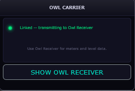
Carrier is intentionally minimal — a small window with a status indicator and a single button. All the measurement display lives in the Receiver. Carrier's only job is to measure audio at its position and transmit the data.
The colored dot on the left of the status card shows the link state at a glance. The SHOW OWL RECEIVER button brings the Receiver window to the front in your DAW without having to hunt for it — useful when you have many plugins open.
Carrier and Receiver have found each other and are communicating. Everything is working correctly.
The plugin order is wrong. Carrier is running after Receiver in the signal chain. Move Carrier to an earlier slot in the FX chain, or an earlier track in the session.
Carrier hasn't found a Receiver yet. Make sure Receiver is loaded on the same session, press Play, and wait a moment.
Owl Receiver — Reading the Meters
Three Meter Columns
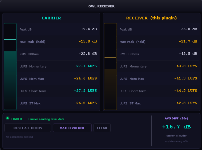
The Receiver window is divided into three vertical columns, each showing a different signal position. All meters refresh at 30 fps.
What Each Meter Row Means
Both the Carrier and Receiver columns display the same seven rows. Understanding what each row tells you is the key to using Owl effectively.
How to Read the Level Bars
Each column has a vertical level bar alongside its numeric readouts. The bar has two layers: a filled level bar that tracks the RMS level in real time, and a peak tick mark near the top that shows the instantaneous peak. When the peak tick approaches the top of the bar, the signal is near 0 dBFS. When the Carrier bar is noticeably taller than the Receiver bar, your processing is attenuating the signal — as expected from a compressor or limiter.
A Receiver bar that is taller than the Carrier bar means your processing is adding gain somewhere in the chain between the two plugins. This might be intentional (a boost EQ, a makeup gain on a compressor) or accidental.
Receiver Controls — Matching & Reset
Avg Diff Panel — Understanding the Number
In the bottom-right corner of the Receiver is the Avg Diff (30s) panel. This shows the rolling 30-second average difference between the Carrier RMS and the Receiver RMS, updated every 5 seconds. It reads Carrier RMS minus Receiver RMS:
Reset All Holds
The RESET ALL HOLDS button clears every max/hold value on both the Carrier and Receiver columns at once. The Receiver sends a reset signal to the Carrier through the shared link, so both plugins clear simultaneously — you do not need to open the Carrier window separately.
Use this whenever you want to start a fresh measurement: after setting levels, after making a major change to your chain, or at the beginning of a new pass. All amber hold values drop back to −inf immediately.
Match Volume (Manual)
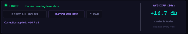
Once the Avg Diff panel has collected enough data (at least ~5 seconds of audio), the MATCH VOLUME button becomes active. Clicking it reads the current Avg Diff value and applies that exact dB correction as a gain offset on the Receiver's output.
For example: if the Avg Diff shows +3.2 dB (Carrier is louder), clicking Match Volume applies +3.2 dB to the Receiver's output, bringing it up to match the Carrier's average level. The Match meter column shows the result after correction is applied.
The gain readout below the buttons shows the currently applied correction: Correction applied: +3.2 dB. This correction is a fixed offset — it does not adapt as levels change. Use Auto Match if you need the correction to stay current as you make adjustments.
Auto Match (Continuous)
AUTO MATCH keeps the level correction continuously updated rather than applying a fixed snapshot. It uses a fast exponential moving average that measures the RMS difference between Carrier and Receiver every ~50ms and updates the applied correction every ~500ms. The status bar reads LINKED — Auto Matching Volume Active in purple when it is running.
This is most useful when you are actively tweaking compressor or EQ settings and you want the Receiver's output to stay loudness-matched to the Carrier continuously as you make changes. Without Auto Match, every parameter change that affects the output level would throw off a manual Match Volume correction.
Click AUTO MATCH again to toggle it off, or click CLEAR to both stop Auto Match and remove the applied correction entirely. The button label changes to AUTO MATCH ON while active.
Clear
CLEAR removes all applied gain correction — both manual Match Volume and Auto Match — and returns the Receiver to unity gain. The Match meter column returns to showing the uncorrected Receiver level. Use this when you want to go back to comparing raw unmatched levels or when you have made a large change to your chain and want to re-analyze from scratch.
Receiver Status Messages
All Status States Explained
The status bar at the bottom of the Receiver window tells you exactly what is happening between the two plugins.
Everything is correct. Both plugins are communicating. Meters are live and accurate.
Linked and Auto Match is running. The Receiver is continuously adjusting its output gain to match the Carrier's level.
Receiver cannot find a Carrier. Either Carrier is not in the session, or both plugins are not running at the same sample rate and block size. Check that Carrier is loaded and that you have pressed Play.
Receiver detected that Carrier is processing audio after it, not before. Swap the plugin order in your FX chain, or move the Carrier track earlier in your session's processing graph.
More than one Owl Carrier instance is running with the same configuration. Remove the duplicate Carrier. Each Carrier/Receiver pair must be unique.
Common Use Cases
Level-Matched A/B of Your FX Chain
Place Carrier at the very start of your FX chain (before any processing). Place Receiver at the end. Play for 30 seconds. Click MATCH VOLUME. Now bypass your entire FX chain in the DAW — the bypassed signal hits the Receiver first (which passes it through without the correction applied since the plugin is active but the chain is bypassed) vs. the full processed version.
The standard approach: keep both Carrier and Receiver active, then use your DAW's FX chain bypass to toggle the processing between them. Because Match Volume compensates for the output level difference the processing creates, what you are hearing when you toggle is the processing quality alone — not the level change it introduces. This is how professional engineers do level-matched A/B comparisons.
Monitoring Pre/Post Compression or Limiting
Place Carrier before your compressor or limiter, Receiver after. Watch the LUFS Short-term readings in both columns while audio plays. The difference between Carrier short-term and Receiver short-term tells you how many dB of loudness reduction the compressor is producing on average over 3 seconds. The RMS 300ms comparison tells you the moment-to-moment gain reduction.
Enable AUTO MATCH and then adjust the compressor's threshold or ratio. Because the output level is continuously corrected, what you are hearing through the Receiver reflects the effect of the compressor's tonal and dynamic shaping — not its loudness change. This lets you dial in exactly the right amount of compression by ear without the louder output biasing your perception.
Loudness Compliance Check
Place Receiver after your master limiter. Watch the LUFS Momentary and LUFS Short-term values in the Receiver column during playback. These are the numbers streaming platforms measure. For Spotify, Apple Music, and most major streaming services the target is around −14 LUFS integrated — your short-term readings should be in this neighborhood during the loudest sections of your track.
Use the Max Peak hold row to confirm that your limiter is keeping the true peak below −1 dBFS (the standard headroom requirement for streaming). If Max Peak ever reaches 0 dBFS or above, your limiter is not catching all inter-sample peaks.
Cross-Track Level Comparison
Place Carrier on a reference track (a professional mix you are comparing against) and Receiver on your own master bus. Both tracks must have the same sample rate and block size. The Receiver shows the reference track's levels in the Carrier column and your own master bus levels in the Receiver column simultaneously. Use this to see at a glance whether your master's LUFS, RMS, and peak readings are in the same territory as the reference.